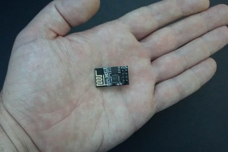
The ESP-01 is a popular, inexpensive microcontroller board with built-in Wi-Fi. It makes use of the, now, widely used ESP8266 microcontroller chip.
Table of contents
Introduction to the ESP8266 microcontroller chip
ESP8266 microcontrollers are designed for communicating over the internet through Wi-Fi radio signals. It has onboard processing and memory that allows it to be integrated with electronics through its GPIOs. With the ESP-01, two GPIO pins are available (GPIO0 and GPIO2).

ESP-01(S) black edition with 1MB flash memory.Today, ESP8266 microcontrollers have been incorporated into many microcontroller boards (e.g. the ESP-01, ESP-02, etc.).
The first ESP8266 chips were developed and manufactured by the Chinese company, Espressif Systems. What makes these chips popular is their full set of networking protocols with Wi-Fi connectivity.
- Get the ESP-01 module (blue) from BangGood or Amazon.com
- Get the ESP-01S module (black) from Amazon or BangGood
- Amazon.com or BangGood
ESP-01 pinout
Power requirements
Even when fully functional, ESP8266 chips are considered low-power consumers. The voltage requirement is 3.3V DC. Typically, the chip draws about 80 – 170 mA. It also supports three lighter power modes: light sleep (0.5 mA), modem sleep (15 mA) and deep sleep (0.1 mA). At certain times (e.g. bootup or when the chip ‘wakes up’ from a sleep mode) the peak operating current can be as high as 320 mA.
3.3V DC power is supplied to the ESP-01 module via the VCC and GND pins. 3.3V also needs to be supplied to the CH_PD pin. Each I/O pin will supply up to 12 mA of current.
ESP-01 specifications
Currently, the ESP-01 has two editions (the older blue edition and the newer black edition — also called the ESP-01S). The main difference between the two editions is that the newer black edition has 1 MB of flash memory whereas the blue edition has 512 KB (basically more space). Some users have also found that a baud rate of 115 200 bps is better to use for the newer edition.
Number of cores: 1
Architecture: 32-bit
CPU clock speed: 80 MHz (default) – 160 MHz (programmable)
Memory: External flash memory chip
Flash memory: 512 KB – 1 MB (edition dependent)
Operating voltage (logic level): 3.6V DC (max)
Input voltage: 2.5 – 3.6V DC, 3.3V DC (recommended)
Power source: GPIO pins (Vc & CH_PD – both need to be connected)
Networking: Wi-Fi (IEEE 802.11 b/g/n) (not available during sleep modes)
Antenna: On-board PCB trace
Standards: FCC/CE/TELEC/SRRC
Frequency range: 2.4G ~ 2.5G (2400 m ~ 2483.5 m)
Tx power: 802.11 b: +20 dBm, 802.11 g: +17 dBm, 802.11 n: +14 dBm
Rx sensitivity: 802.11 b: -91 dbm (11 Mbps), 802.11 g: -75 dbm (54 Mbps), 802.11 n: -72 dbm (MCS7)
Security modes: WPA, WPA2
Encryption: WEP/TKIP/AES
Network protocols: IPv4, TCP/UDP/HTTP/FTP
Bluetooth: none
Digital I/O (read/write) pins: 2 (GPIO0 & GPIO2)
On-board LED pin: GPIO1 (also doubles as Tx pin)
Analog input pins: none (can be manipulated through programming)
Operating current: mode dependent, sleep modes about 0.1 mA to 15 mA, during Rx/Tx (Wi-Fi) about 80-170 mA, peak at approx 320 mA
Operating current per I/O pin: 12 mA
Size: 25 x 14.5 mm
Operating temperature: -40 ~ 125 °C
Interfaces: Serial/UART, SDIO, SPI
Ports: none
Breadboard friendly: no
Pin size: male, 5 x 2.54 mm
The software
Although the ESP8266 chip has 17 GPIO pins, the ESP-01 only has three working pins (one is connected to the blue onboard LED). The ultimate goal is to be able to control these three pins using Wi-Fi. In order to achieve this, the chip needs software — called firmware. The firmware allows access to the chip, and determines what commands can be used and how to respond to them.
Terms such as ‘flashed’ and uploaded are commonly used for the process of adding software to a microcontroller. Programming (or ‘flashing’) refers to uploading (custom or pre-configured) software (or firmware) to the ESP8266’s flash memory — where it is stored until it is flashed again. Flashing is done using a serial-UART interface. For more software information, see the Programming libraries section below.
Boot modes
The ESP8266 chip has (at least) two different boot modes: ‘normal mode’ and ‘programming mode’. To be able to upload new software/firmware to the chip, it needs to boot into programming mode. Flashing will overwrite the previous software (including the AT command set if that was flashed).
Programming
The ESP8266 has a built-in UART (universal asynchronous receiver/transmitter) which can be used for TTL serial communication and/or flashing the chip. To be able to use the UART, a 3.3V USB to TTL serial converter is required. The USB to TTL serial converter must be able to supply at least 300 mA.

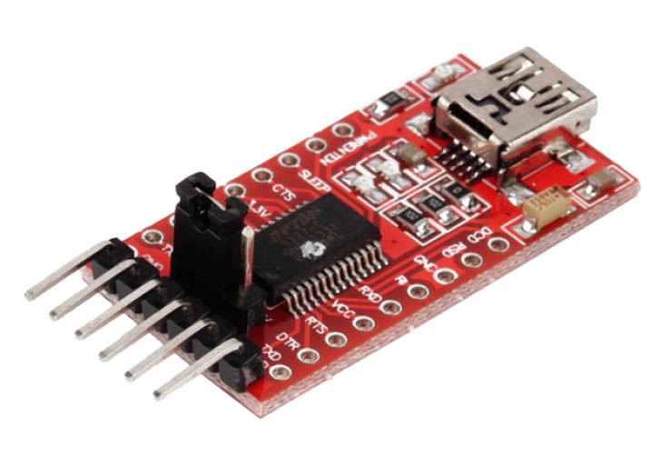
FTDI USB to TTL serial converter module with a 5/3.3V DC voltage regulator, a mini-B USB port and Rx/Tx pins.
There is more than one serial to USB converter option available. With the correct information, an Arduino can also be used.
A good option includes the FTDI USB to TTL serial converter module. It has a 3.3/5V DC jumper and will supply 500 mA through its Vc pin.
- Get the FT232RL FTDI USB To TTL Serial Converter Module from Amazon.com or BangGood
- Get the 6 Pin FTDI FT232RL USB To Serial Cable from Amazon.com or BangGood
- Get the Basic Arduino Uno R3 Starter Kit from Amazon.com or BangGood
Programming libraries
The ESP-01’s current firmware can be replaced using downloadable or custom software written with an appropriate software development kit (SDK). There are a few different firmware, software and SDK options available.
AT command processors
Many ESP-01s will come pre-programmed with firmware that uses AT commands. Various other ESP8266 AT command processor firmware options are available for download on the internet.
When an AT command processor is installed, AT commands can be used to change some of the default hardware settings or to trigger the GPIO pins. Although the AT command set is stored in the memory, the hardware settings, e.g. after being changed, are not — meaning that these settings need to be updated after each boot.
AT commands can be given using a serial-UART interface or by using an external software application (TCP connection software) that can send commands over Wi-Fi using the same baud rate that was set up on the ESP8266.
With this option, no specific programming language, just the AT commands, is necessary to be able to use the module.
Fortunately, Espressif made a Software Development Kit (SDK) available that allowed users to flash different firmware options to the ESP8266.
NodeMCU
NodeMCU is one of the more popular alternatives for firmware running on the ESP8266. It runs a Lua interpreter on the ESP8266 processor, which can execute commands written in the Lua scripting language (almost like a little operating system).
Lua script files are written and saved in .lua format. NodeMCU allows GPIO and hardware functionality such as i2c and PWM. These script files also allow the setup of hardware settings.
With this option, the user has access to an extensive range of the Lua functions and sample code for writing their own applications.
Arduino IDE
More recently, the ESP8266 community created an add-on for the Arduino IDE that allows Arduino-like (C or C++) programming to be uploaded as software. The ESP8266 is added as a third-party ‘core’ using the Boards Manager.
This option uses a compiled solution. There is no interpreter. The Arduino IDE takes a sketch, includes the related library functions and compiles it to produce a standalone piece of firmware in the form of a binary file. The entire binary file is then uploaded to the ESP8266.
Script files (or more specifically sketch files) are written and saved in .ino format. Arduino IDE sketches allow GPIO functionality and allow the setup of hardware settings.
By adding the ESP8266 core to the Arduino IDE, an extensive range of libraries and sample code is also added.
Other
For advanced users, there is the esp-open-sdk toolchain which allows direct programming to the ESP8266. Python (MicroPython) and Javascript (Espruino) can also be used, but at the time of writing, all these packages were still in early development.
Other features
Like many microcontroller boards, the ESP-01 has an onboard power (red) LED and a Wi-Fi indicator/Tx (blue) LED. The blue LED and Serial.print() commands cannot be used at the same time.
Conclusion
The ESP8266 microcontroller is designed for communicating over the internet. Although tiny, it has onboard processing and memory that allows it to be integrated with electronics through its GPIOs.


