ESP8266 5V Wi-Fi relay switch modules are Wi-Fi enabled, relay power switches with an ESP-01 board. They can be controlled wirelessly from smart devices.
Table of contents
Introduction to ESP8266 5V Wi-Fi relay switch modules
As the name implies, ESP8266 5V Wi-Fi relay switch modules are Wi-Fi-enabled, relay power switches. The module includes a detachable ESP8266 microcontroller board. The main function of these boards is to be used as wireless power switches accessible from Smartphones.
The ESP8266 5V Wi-Fi relay switch module is a small, inexpensive module measuring in at 45 x 28 x 20 mm and needs 5V DC to operate. Similar to other Songle relay switch modules, the onboard relay can tolerate 110 – 250V AC or up to 30 V DC at 10A. The module is also equipped with serial port debugging pins and has a built-in ‘flyback’ diode to protect the circuit from voltage spikes.
ESP8266 5V Wi-Fi Relay switch module specifications
Chip: ESP8266
DC Pins: 3. IN, VCC, GND / S, +, – (marked).
AC Sockets: 3. NO (normal open), COM, NC (normal closed) (marked)
Working voltage: 5V DC (connected via screw terminal connectors). 12V DC modules also available
Operating current: >1000 mA (1000 mA tested successfully)
Serial port debugging pins: Tx, Rx, Vcc, GND (marked)
Board baud rate (MCU STC15F104W): 9600 bps, but 115200 bps is also been reported to work in some cases
ESP-01 baud rate: default is 115200 bps, is set to 9600 through programming
Interfaces: Serial/UART
On-board LED: yes
Size: 45 x 28 x 20 mm (L,W,H). Might be module dependent.
Pin size: male, 5 x 2.54 mm
Weight: 40 g
The ESP-01 module
The ESP8266 5V Wi-Fi relay switch module is shipped with a detachable ESP-01S microcontroller board. It will most likely be the black edition (ESP-01s) with 1 MB of flash memory. Out of the box, this module is flashed with an AT command firmware (AI-Thinker firmware).
By using the serial port debugging pins settings for things such as the working mode (see below), baud rate, TCP server port and the number of connections can be set, but these need to be re-programmed each time the module was disconnected from power.
The ESP8266 5V Wi-Fi relay switch module automatically reduces the input voltage of the ESP8266 to 3.3V DC.
Setting up the ESP8266 5V Wi-Fi relay switch module
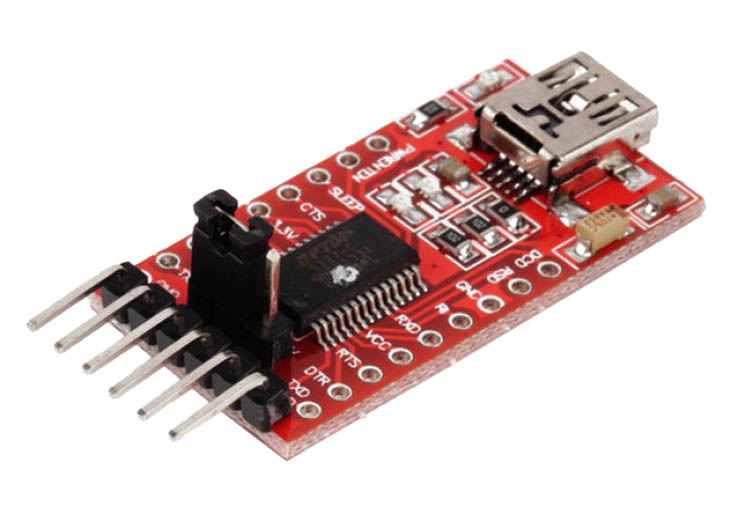
Out of the box, some option settings of the ESP8266 5V Wi-Fi relay switch modules need to be set (see The ESP-01 module above). Depending on its purpose/desired working mode (see below), serial commands need to be sent to the module using its serial debugging pins and serial debugging software (see below). The pins are to be connected to a USB to TTL serial converter, e.g. FTDI USB to TTL serial converter module, which, in turn, is connected to a PC via a USB port.
Unfortunately, the default process of setting up an ESP8266 5V Wi-Fi relay switch module is impractical. The biggest downfall of these modules is that the options settings will be lost each time power is disconnected from the module. This means that the module needs to be installed and connected to its functional environment before the option settings can be set.
Working modes
ESP8266 5V Wi-Fi relay switch modules can be used as stand-alone Wi-Fi connected device (AP or access point mode) or can be connected (on)to a local area network (STA or station mode). With AP mode up to 5 connections can be made at the same time and it is said that a connection can be made from as far as 400 meters away.
Either way, connection and communication to the module are made by using a TCP connection App (such as EasyTCP for Android). Baud rates of 115200 or 9600 bps can be used.
The process itself can be seen here.
To get started with the ESP8266 5V Wi-Fi relay switch modules you will need
- ESP8266 5V Wi-Fi relay switch module Amazon.com or BangGood
- Smartphone
- A personal computer to be able to do debugging
- Serial port debugging software Download ‘Terminal’
- FTDI USB to TTL serial converter module Amazon.com or BangGood
- Mini-B USB cable Amazon.com or BangGood
- 5 V DC 1A power supply converter module Amazon.com or BangGood
- Female-female breadboard jumper wire cables (optional) Amazon.com or BangGood
Power considerations
Although the ESP-01 and relay switches on their own are considered fairly low power consumers (300 mA and ~0.45 Watts respectively), the ESP8266 5V Wi-Fi relay switch modules need a fair amount of current to operate.
I tested two power supply converter modules (5V/700mA and 5V/1000mA). The module only functioned normally when 1000mA current was applied.
Conclusion
Although proper instructions might be hard to come by, ESP8266 5V Wi-Fi relay switch modules are still inexpensive and small enough to incorporate into DIY projects. Although the programming can be a bit confusing and impractical, these modules are great to be used as Smartphone operated trigger switches for high voltage units like lights in Home automation projects.


