Here we explain how to get up and running with the 433MHz RF Transmitter Receiver modules to send RF signal-codes from a transmitter device to a Raspberry Pi.
Table of contents
Introduction to 433MHz RF communication to a Raspberry Pi
433MHz RF communication is a popular wireless communication technology that operates in the unlicensed frequency band of 433MHz. It is widely used in various applications, including home automation, remote controls, and wireless sensor networks.
The Raspberry Pi, a popular single-board computer, can be easily integrated with 433MHz RF modules to enable wireless communication between devices, sensors, or actuators. This combination provides a powerful platform for building wireless systems that can be controlled or monitored remotely.
This post will show how to connect a Raspberry Pi to a 433MHz RF Receiver module by using its GPIO pins. This will enable the Raspberry Pi to receive radio frequency (RF) signals from a 433MHz RF Transmitter module.
In this case, the transmitter module will be connected to an Arduino, but other devices can also be used. Communication takes place using specific RF signal codes generated using Python.
- Get the Raspberry Pi 4B 4GB Starter Kit from Amazon.com
- Get the Raspberry Pi 4B 8GB Starter Kit from Amazon.com
- Get the Basic Arduino Uno R3 Starter Kit from Amazon.com or BangGood
- Get the 433Mhz RF Transmitter Receiver Module Kit from Amazon.com or BangGood
Requirements and assumptions
A fully functional Raspberry Pi with the Raspberry Pi OS (formerly known as Raspbian) installed was used. Initially, a connection to the internet will be needed to install the required libraries. The command line, Bash, or a Python script will be used to receive the RF signals.
Input to the Raspberry Pi will be required for installation, setup, coding, and testing purposes. PuTTY and/or WinSCP can be used to connect to the Raspberry Pi from a remote PC in the case where a screen, keyboard, and mouse are not connected to the Raspberry Pi.
You will also need:
- At least 2 pairs of 433 MHz Transmitter Receiver units Amazon.com or BangGood
- 433 MHz Spiral Spring Helical Antennas (optional), but will help to extend the range between communicating units Amazon.com or BangGood
- Solderless developing breadboard and some additional breadboard wiring (Arduino and Raspberry Pi compatible) Amazon.com or BangGood
- Functional Arduino connected to a serial monitor. We used an Arduino Nano, but any Arduino with a USB connection can be used.
Setting up the Arduino to transmit RF signals
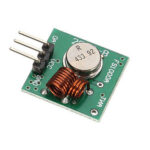
 This will set the Arduino up as the transmitter. To do so grab the square (vs. longer) module from your 433MHz RF Transmitter Receiver module pair.
An antenna can be added to increase the transmission length of the transmitter module. Generic mini antennas can be used or you can make one yourself by coiling a 25 cm 1 mm solid wire and soldering it to the antennae hole (marked).
On the Arduino, the RC Switch library needs to be available in the Libraries directory. To add this library to the Arduino IDE, select the latest downloaded zip-file from Add .ZIP Library… from the Include Library option under the Sketch menu.
On a Linux system (i.e. if the Arduino IDE is used on a Raspberry Pi with Raspbian) the following terminal commands are used to clone the latest version of the RC Switch library directly into the Arduino IDE libraries folder:
sudo apt-get install git
cd /home/pi/sketchbook/libraries
git clone https://github.com/sui77/rc-switch.git
To prevent Java errors, rename the /rc-switch directory to /rcswitch using the mv terminal command:
mv /home/pi/sketchbook/libraries/rc-switch /home/pi/sketchbook/libraries/rcswitch
The pins on the 433MHz RF Transmitter module are clearly marked. Connect the breadboard wiring as follows:
- ATAD (DATA) to the D10 pin of the Arduino
- VCC (5V) to the 5V pin of the Arduino
- GND to the GND pin of the Arduino
Connect the Arduino to the Arduino IDE and upload the following sketch:
#include <RCSwitch.h>
RCSwitch mySwitch = RCSwitch();

void setup() {
  Serial.begin(9600);
  // Transmitter is connected to Arduino Pin #10
  mySwitch.enableTransmit(10);

  // Optional set pulse length.
  // mySwitch.setPulseLength(320);

  // Optional set protocol (default is 1, will work for most outlets)
  // mySwitch.setProtocol(2);

  // Optional set number of transmission repetitions.
  // mySwitch.setRepeatTransmit(15);

}

void loop() {
  /* Using decimal code */
  mySwitch.send(1234, 24);
  Serial.print("Attempting to send 1234");
  delay(4000);
  mySwitch.send(4321, 24);
  Serial.print("Attempting to send 4321");
  delay(4000);

  /* Using binary code */
  //mySwitch.send("000000000001010100010001");
  //delay(1000);
  //mySwitch.send("000000000001010100010100");
  //delay(1000);*/
}
This code will instruct the Arduino to send the decimal code ‘1234‘, wait for four seconds, and then send ‘4321’.
It will turn over and over until the Arduino is switched off. Binary codes and also be tested by removing the //‘s from the bottom section of the code.
Other important things to notice here are the inclusion of the library and the setting up of the transmitter to pin D10.
Give the Arduino power and connect the IDE to the Serial Monitor. The code should show that it is being sent.
Setting up the Raspberry Pi to receive RF signals
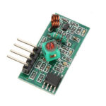
 To set the Raspberry Pi as the receiver, take the longer (vs. square) module from the 433MHz RF Transmitter Receiver module pair and add an antenna again. wiringPi and a modified version of 433Utils. will be used.
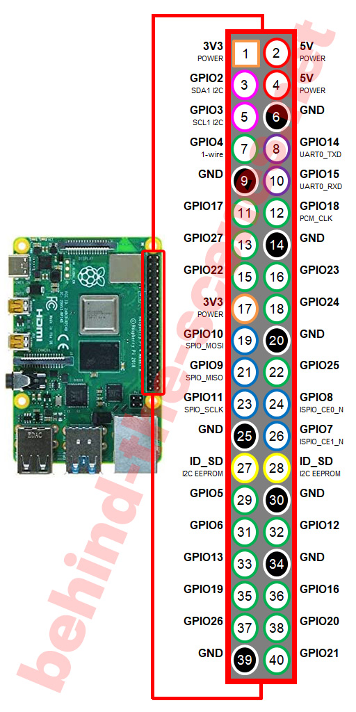
When positioning the Raspberry Pi GPIO pins facing up and on the opposite side of you, i.e. with the USB and Ethernet port on the right, the physical GPIO pin numbering will be as follows:
The pins on the 433MHz RF Receiver module are clearly marked. The receiver module has two DATA pins. As a rule, I like to always use the DATA pin closest to GND. While the Raspberry Pi is switched off, connect the breadboard wiring as follows:
- ATAD (DATA) to physical GPIO pin number 13 (i.e. GPIO27)
- VCC (5 V) to physical GPIO pin number 2 or 4
- GND to physical GPIO pin numbers 6, 9 or 14
To install wiringPi the git clone command will be used. The following terminal commands can be used from the /home/pi directory:
sudo apt-get install git
git clone git://git.drogon.net/wiringPi
cd wiringPi
./build
After wiringPi is installed, the build can be checked at any time with:
gpio readall
which, if correctly installed will give the state of each pin on the GPIO:
+----------+-Rev1-+------+--------+------+-------+
| wiringPi | GPIO | Phys | Name   | Mode | Value |
+----------+------+------+--------+------+-------+
|      0   |  17  |  11  | GPIO 0 | OUT  | Low   |
|      1   |  18  |  12  | GPIO 1 | IN   | Low   |
|      2   |  21  |  13  | GPIO 2 | IN   | Low   |
|      3   |  22  |  15  | GPIO 3 | IN   | Low   |
|      4   |  23  |  16  | GPIO 4 | IN   | Low   |
|      5   |  24  |  18  | GPIO 5 | IN   | Low   |
|      6   |  25  |  22  | GPIO 6 | IN   | Low   |
|      7   |   4  |   7  | GPIO 7 | IN   | Low   |
|      8   |   0  |   3  | SDA    | IN   | High  |
|      9   |   1  |   5  | SCL    | IN   | High  |
|     10   |   8  |  24  | CE0    | IN   | Low   |
|     11   |   7  |  26  | CE1    | IN   | Low   |
|     12   |  10  |  19  | MOSI   | IN   | Low   |
|     13   |   9  |  21  | MISO   | IN   | Low   |
|     14   |  11  |  23  | SCLK   | IN   | Low   |
|     15   |  14  |   8  | TxD    | ALT0 | High  |
|     16   |  15  |  10  | RxD    | ALT0 | High  |
+----------+------+------+--------+------+-------+
Note above how the physical GPIO pin numbers change. Physical GPIO pin number 11 for example becomes GPIO 0 with wiringPi. We used the physical GPIO pin 13, so it will become GPIO 2.
To install 433Utils onto the Raspberry Pi go to the /home/pi directory and use the following git clone terminal commands:
cd /home/pi
git clone --recursive git://github.com/ninjablocks/433Utils.git
cd 433Utils/RPi_utils
make
To receive RF signal codes, we will be using RFSniffer.cpp. To see its content, the nano terminal command can be used:
sudo nano /home/pi/433Utils/RPI_utils/RFSniffer.cpp
Nothing has to be changed for now. Because the DATA pin of the 433MHz RF Receiver module was connected the GPIO 2 of wiringPi can be used. Press Ctrl + X to exit back to the terminal.
If the code was changed, in order to use the newest version of RFSniffer.cpp it needs to be compiled again:
cd /home/pi/433Utils/RPI_utils/
make RFSniffer.cpp
Testing the communication
While the Arduino is sending the code, the ‘sniffer’ can be activated on the Raspberry Pi with the following terminal command:
cd
sudo /home/pi/433Utils/RPi_utils/RFSniffer
The terminal will now be waiting for RF signals. If a signal is received it will be displayed on the terminal screen. There might be other random pieces of code in between, but it should mainly show ‘1234’ followed by ‘4321’.
Conclusion
A Raspberry Pi connected to a 433MHz RF Receiver module can be used to receive RF signals using one of its DATA pins. This post showed how to use a Raspberry Pi to receive 433 radio frequency signals from an Arduino connected to a 433MHz RF Transmitter module.


Hello,
Is it possible to do this using two raspberry pies, rather than and raspberry pie and an Arduino?
Thank you so much,
RG
Brilliant – been playing around with these 433 MHz modules all day and finally got it working thanks to your clear example. Thanks mate!
So what is the code if I wanted to transmit from the Raspberry Pi and receive on the arduino?
not sure
Is it possible to use this connection to send terminal commands to and from a raspberry pi?
THank you for the post !!
I succeeded to communicate between Arduino and RaspBerry.
I have a litle trouble, when i receive on on the RaspBerry. The text Received 4321, appears one or two or three times …
Have you a clue about this behavior ?
Thank you for your help.
Hi Yvonne
Like a remote control?
Hi,
Thank you for this article.
Can you do the same with an RF remote and receiver?
Thank you for your reply.
Kind regards,
Yvonne