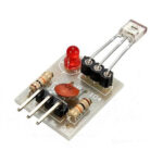
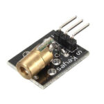
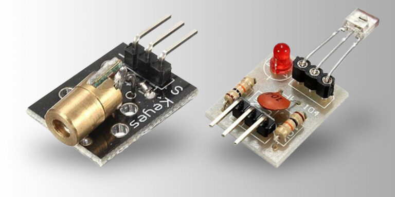
Laser transmitter and receiver modules are small, cheap and readily available modules that can be used to detect motion.
Table of contents
Introduction to laser transmitter and receiver modules
Laser transmitter and receiver modules are electronic devices that use laser light to transmit and receive information between two points. These modules are commonly used in remote sensing applications.
The laser transmitter module consists of a collimated laser diode that can produce a straight, non-diverging laser beam). The laser receiver module consists of a separate non-modulating laser tube sensor which acts as a laser beam sensor. Both these modules also consist of associated electronic circuitry that converts electrical signals into laser light and vice versa.

The Laser transmitter module is small and cheap which makes it easy to incorporate into personal projects.
In combination, the transmitter emits a laser beam onto the receiver to trigger an on-off signal. Both the transmitter and receiver modules can be connected to a microcontroller (e.g. the Arduino, Raspberry Pi or ESP modules) using their power and digital pins.
- Get the Laser Transmitter & Receiver module from Amazon.com
- Get the Basic Arduino Uno R3 Starter Kit from Amazon.com or BangGood
- Get the Microelectronics Starter Kit from Amazon.com or BangGood
Sample uses & alternatives
The Laser Transmitter Receiver modules are probably mostly used in security projects for motion detection at night. With a bit of extra programming, I assume they can be used with the same principles to detect the direction of movement too.
Although not carrying any data per se (non-modulated), Laser Transmitter Receiver Modules can also be used for very basic short-distance wireless communication in the form of signaling.
Other motion detection modules include the HC-SR501 Pyroelectric Infrared Motion Sensor modules and more specific wireless communication modules include the 433MHz RF Transmitter Receiver modules, XBee (IEEE 802.15.4-2003 ) point-to-point modules, Bluetooth modules and the increasingly popular ESP8266-related Wi-Fi modules.
Important things to know
The sensor uses a non-modulated laser receiver, so only on-off signals can be triggered. It is also recommended for use indoors or in dark environments. Sunlight or other light fixtures may interfere with the signaling.
Accuracy is very important. Proper, solid mounting of both the transmitter and sensor modules will be required.
Laser Transmitter Receiver modules specifications
Receiver unit
 Pins: 3. GND, OUT, VCC (marked).
Trigger mode (digital read): HIGH w/ laser contact, LOW w/o laser contact
Input voltage: 5 V DC
Level output: 5 V DC high, 0 V low
Size: 15 x 19 mm or 15.2 x 22.2 mm
Breadboard friendly: yes
Pin size: male, 5 x 2.54 mm
Transmitter unit
 Pins: 3. Gnd, Out, Vcc (Out is marked S & Vcc marked -).
Trigger mode (digital write): High to low
Input voltage: 5V DC
Level output: 5V DC low, 0V high
Size: 15 x 24 mm
Wavelength: 650 nm
Depth: 8 mm
Weight: 2.2 g
Breadboard friendly: yes (but impracticable)
Pin size: male, 5 x 2.54 mm
Transmitting range: ?
Example code
Laser transmitter module
To trigger a signal on the laser transmitter module, a digital output pin on an Arduino can be used. The following code will activate the digital pin using the Arduino IDE:
const int laserPin = 13; // Digital pin connected to the laser module

void setup() {
  pinMode(laserPin, OUTPUT); // Set the laser pin as an output
}

void loop() {
  digitalWrite(laserPin, HIGH); // Turn on the laser
  delay(1000); // Wait for 1 second
  digitalWrite(laserPin, LOW); // Turn off the laser
  delay(1000); // Wait for 1 second
}
In this code, we define laserPin as the digital pin connected to the laser module. In the setup() function, we set the laserPin as an output pin using pinMode().
In the loop() function, we turn on the laser by setting the laserPin to HIGH using digitalWrite(), then we wait for 1 second using delay(). After that, we turn off the laser by setting the laserPin to LOW and wait for another 1 second before repeating the process.
Laser receiver module
To receive a signal on the laser receiver module, a digital input pin on an Arduino can be used. The following code will activate the digital pin using the Arduino IDE:
void setup() {
  pinMode(receiverPin, INPUT); // Set the receiver pin as an input
  Serial.begin(9600); // Initialize serial communication
}

void loop() {
  int laserStatus = digitalRead(receiverPin); // Read the laser status

  if (laserStatus == HIGH) {
    Serial.println("Laser detected!"); // Print a message when laser is detected
  } else {
    Serial.println("No laser detected."); // Print a message when no laser is detected
  }

  delay(1000); // Wait for 1 second before reading again
}
In this code, we define receiverPin as the digital pin connected to the receiver module. In the setup() function, we set the receiverPin as an input pin using pinMode(). We also initialize serial communication using Serial.begin() to enable communication with the computer for printing the laser status messages.
In the loop() function, we read the status of the laser by using digitalRead() on the receiverPin and store the result in the laserStatus variable. If the laserStatus is HIGH, it means the laser is detected, and we print “Laser detected!” using Serial.println(). If the laserStatus is LOW, it means no laser is detected, and we print “No laser detected.” using Serial.println().
Recommended accessories
- Laser Transmitter module Amazon.com
- Laser Receiver module Amazon.com or BangGood
- Female to female jumper cables Amazon.com or BangGood
- Male to female jumper cables Amazon.com or BangGood
- Solderless developing breadboards Amazon.com or BangGood
- Breadboard wiring Amazon.com or BangGood
Get the Basic Arduino Uno R3 Starter Kit from Amazon.com or BangGood
Conclusion
With their ease of use, price, and availability, Laser Transmitter Receiver Modules are fairly easy to incorporate into micro-electronic projects for example with Arduinos, Raspberry Pis, and ESP-01 modules.
They are great to be used as motion sensing/detection units and can be applied to various security, sensing, and monitoring projects.

