The Raspberry Pi is equipped with a set of GPIO pins, which can be used to connect the Raspberry Pi to other devices, modules and electronic components.
Table of contents
Introduction to the GPIO pins of the Raspberry Pi
Raspberry Pi’s have a set of general-purpose input/output pins (aka GPIO pins) which are directly connected to the CPU of the Raspberry Pi. These pins can be used to read and send information, allowing the Raspberry Pi to interact with other electronic devices.
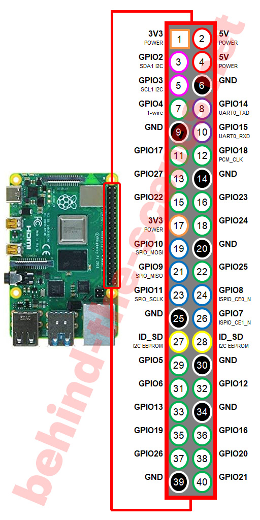
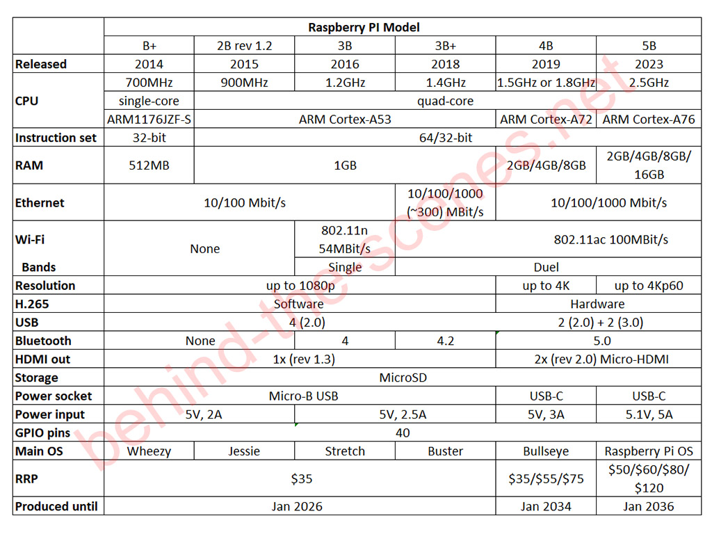
The newer Raspberry B Models, including the Raspberry Pi 2, 3, 4 and 5, all have a total of 40 GPOI pins. The older Model A-boards have a total of 26 pins. The Raspberry Pi Zero and Raspberry Pi Zero W have 40 unpopulated/headerless pins (holes). Pins are aligned as two equal rows (i.e. 2x 20 or 2x 13).
The pins include 5V (2), 3.3V (2), ground (5 for model As & 8 for model Bs) and a few other pins mentioned below. Apart from sensing high and low signals, some of the GPIO pins also double for other functions.
Through, for example, Linux Bash and Python programming, complex logic to and from these pins can be programmed to interact with various microelectronic components such as LEDs, switches, buttons, fans, communication and display modules. The networking capabilities and the control of various USB devices make the possibilities almost endless.
- Get the Raspberry Pi 4B 4GB Starter Kit from Amazon.com
- Get the Raspberry Pi 4B 8GB Starter Kit from Amazon.com
- Get the Raspberry Pi GPIO Breakout Board with Ribbon Cable from Amazon.com or BangGood
Raspberry Pi GPIO specifications
Model B
Operating voltage (logic level): 3.3V DC
Input voltage: 5V DC
Power source: 5V via Micro-B (2nd & 3rd generation), USB-C (4th generation) or GPIO I/O pins
Digital I/O (read/write) pins: 22
Interrupt pins: all
Analogue input pins:
Operating current (per I/O pin): ~8 mA (15 mA max) (50 mA max all)
Interfaces: Serial/UART (GPIO 14 & 15), SPI, I2C
Breadboard friendly: na
Pin size: male, 5 x 2.54 mm
Raspberry Pi Model B GPIO pinout
There are two ways to refer to the GPIO pins of the Raspberry Pi:
- by name (also known as the Broadcom numbering), or
- by pin number (which corresponds to the pin’s physical location)
For example, GPIO 25 corresponds to pin 22 (see below).

Example of a Raspberry Pi Model B GPIO pinout. This pinout is commonly used when for e.g. using the Wiring Pi Python library. Other libraries might use a different pinout.
Output pins
A GPIO pin designated as an output pin can be set to HIGH (3.3V) or LOW (0V). Output pins are used for example LEDs.
Input pins
A GPIO pin designated as an input pin can be read as HIGH (3.3V) or LOW (0V). This is made easier with the use of internal pull-up or pull-down resistors. Pins GPIO2 and GPIO3 have fixed pull-up resistors, but for other pins, this can be configured in software.
Interrupt pins
On the Raspberry Pi, each GPIO pin can also be configured as an interrupt pin.
Serial pins
The Raspberry Pi is capable of serial communication with other devices. Tx (GPIO14) and Rx (GPIO15) pins use 0 and 3.3 V TTL (transistor-transistor logic) to produce their signal.
Accessing the GPIO pins of the Raspberry Pi
The GPIO pins of the Raspberry Pi can be accessed directly or indirectly using a shield or a pin extension cable or a module.
Direct linking, for example, to a breadboard, can be achieved using female Dupont cables:
- Get the Male To Female Jumper Cables from Amazon.com or BangGood
- Get the Female To Female Jumper Cables from Amazon.com or BangGood
- Get the Solderless Breadboards (8.5×5.5cm) from Amazon.com or BangGood
Indirect access to the GPIO pins of the Raspberry Pi can be made using shields or pin extension cables and modules:
- Get the Raspberry Pi GPIO Edge Expansion Board from Amazon.com or BangGood
- Get the Raspberry Pi GPIO Breakout Board with Ribbon Cable from Amazon.com or BangGood
- Get the GPIO Breakout Kit for the Raspberry Pi from Amazon.com
Raspberry Pi GPIO libraries
There are a couple of libraries available to be able to utilise the GPIO pins of the Raspberry Pi. GPIOZero (which is included by default in the Raspberry Pi OS image) and Wiring Pi are fairly comprehensive. Other, less-developed libraries include RPi.GPIO, pi-gpio and raspberry-gpio-python.
GPIOZero
The gpiozero library provides a collection of interfaces for common components such as LEDs, buttons, potentiometers, sensors, etc.
Instead of setting the GPIO properties to control an LED, gpiozero provides an LED interface with methods that are useful to control LEDs. The DigitalOutputDevice interface can also be used to control digital outputs in general (including LEDs).
The gpiozero library should already be installed if you’re running Raspberry Pi OS. If this is not the case, gpiozero can be installed using the python3 -m pip gpiozero terminal command:
python3 -m pip gpiozero
Using a breadboard, connect physical pin 11 to the long pole of an LED and the short pole to a ~220 Ohm resistor before connecting it back to the GND pin (e.g. physical pin 6) of the Raspberry Pi GPOI.
- Get the Solderless Breadboards (8.5×5.5cm) from Amazon.com or BangGood
- Get the Male To Female Jumper Cables from Amazon.com or BangGood
- Get the Diode LED Value Pack (5mm) from Amazon.com or BangGood
- Get the Metal Film Resistor Value Pack (10Ohm – 1MOhm) from Amazon.com or BangGood
- Get the Microelectronics Starter Kit from Amazon.com or BangGood
The GPIO Zero library is used with Python 3. To create a Python file called blink.py, the nano terminal command can be used:
nano /home/pi/blink.py
Do not close the file, yet.
Copy and paste the following code into blink.py:
from gpiozero import LED
from time import sleep

led = LED(17)  # GPIO pin 17 connected to LED

while True:
    led.on()   # turn on LED
    print("LED on")
    sleep(1)   # wait for 1 second
    led.off()  # turn off LED
    print("LED off")
    sleep(1)   # wait for 1 second
In this example, we first import the LED class from the GPIOZero library and the sleep function from the time module. We then create an LED object and connect it to GPIO17, which is where the LED is connected. Note that GPIOZero uses the pin name (i.e. GPIO17 is physical pin 11 on the Raspberry Pi’s GPIO).
In the while loop, we turn the LED on using the on() method, print “LED on” to the console, and wait for 1 second using the sleep() function. We then turn the LED off using the off() method, print “LED off” to the console, and wait for 1 second again.
This process will continue indefinitely until the program is stopped. You can modify the program to fit your specific use case by adjusting the GPIO pin number, the sleep time, and the actions you want to perform when the LED is on or off.
To close save and exit blink.py: press Ctrl + X, then Y.
To run blink.py: the python 3 terminal command can be used:
python3 /home/pi/blink.py
To stop the code press Ctrl + Z.
Case scenarios
Active cooling fan
Cooling fans that add active cooling to the Raspberry Pi’s board are popularly used. 3.3V DC and 5V DC fans can be connected to the GPIO pins of the Raspberry Pi.
In the case where a 5V fan is used, the V+ wire (usually red) is connected to pin 2 or pin 4 of the Raspberry Pi GPIO and the GND wire (usually black) is connected to pin 6. In the case where a 3.3V fan is used, the V+ wire is connected to pin 1 of the Raspberry Pi.
Conclusion
The Raspberry Pi has an extensive set of general-purpose input/output GPIO pins that are connected to the CPU of the Raspberry Pi. This post gave a short introduction to using the GPIO pins of the Raspberry Pi.


